
ISO 6162-1 (SAE J 518 Code 61)
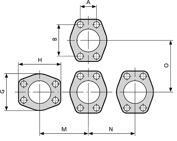
Dimensions for flange connections according to ISO 6162-1.
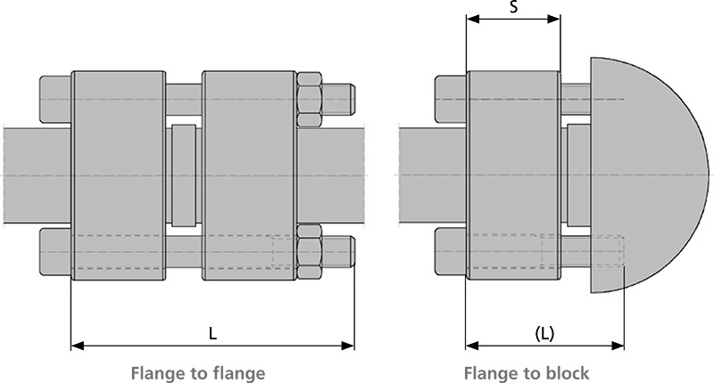
| SIZE | GS-FLANGE TYPE | A | B | G | hrs | M | N | O | S | E | BOLT L DIN 912, 8.8 | WP[BAR] |
|---|---|---|---|---|---|---|---|---|---|---|---|---|
| 1/2" | 608 | 18.2 | 40.5 | 48 | 56 | 57 | 53 | 61 | 20 | 24 | M8x60(35) | 420 |
| 3/4" | 612 | 23.8 | 50.8 | 60 | 71 | 70 | 65 | 76 | 25 | 29 | M10x70(40) | 420 |
| 1" | 616 | 27.8 | 57.2 | 70 | 81 | 80 | 75 | 86 | 25 | 29 | M12x70(45) | 420 |
| 1 1/4" | 620* | 31.8 | 66.7 | 78 | 95 | 91 | 83 | 100 | 30 | 35 | M12x90(50) | 420 |
| 1 1/4" | 621** | 31.8 | 66.7 | 78 | 95 | 91 | 83 | 100 | 30 | 35 | M14x90(50) | 420 |
| 1 1/2" | 624 | 36.5 | 79.4 | 95 | 113 | 109 | 100 | 118 | 35 | 40 | M16x100(60) | 420 |
| 2” | 632 | 44.5 | 96.8 | 114 | 133 | 129 | 119 | 139 | 40 | 45 | M20x110(70) | 420 |
| 2 1/2" | 640 | 58.7 | 123.8 | 150 | 175 | 169 | 156 | 183 | 50 | 55 | M24x140(90) | 420 |
| 3” | 648 | 71.4 | 152.4 | 178 | 215 | 202 | 184 | 218 | 50 | 58 | M30x160(100) | 420 |